Portescap
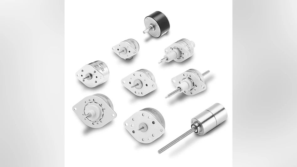
For OEMs, stepper motors can provide advantages over miniaturized DC motors, especially for compact size applications ranging from pharmaceutical dispensers to printers and copiers that require cost-effective and precise positioning. To select the right stepper motor, it’s critical that its pull-out and pull-in torque curves are considered. Understanding these attributes, as well as how to measure them, is a crucial aspect for the design of stepper motion systems.
Valentin Raschke, Application Engineer at Portescap,explains the impact for stepper motor specification.
Unlike a brushless DC motor, the torque generated by a stepper motor depends significantly on rotor position. This means that for a stepper motor, the process of switching between phases, known as commutation, takes place with an external signal. This signal is measured in steps per second that provides four full steps over one mechanical revolution. It’s also the reason for the ‘stepper’ name the motor carries.
Each current pulse achieves one ‘step’ of the motor, so as a result, stepper motors are typically run without feedback. However, this means that the rotor’s position is unknown. Without the ability to precisely measure rotor position, and as the rotation angle is proportional to input current pulses, correctly sizing a stepper motor becomes crucial. To achieve this, knowledge of the motor’s pull-out and pull-in torque should be applied.
What is pull-out and pull-in torque?
Pull-out torque is used to define what torque and speed range the motor can be safely driven in open loop while maintaining its synchronization. This means that if the maximum pull-out torque is exceeded, the motor will fall out of step. For this reason, the maximum load torque is usually set with a safety factor of 30%.
Pull-out torque is also used to determine the motor’s optimal acceleration profile. If acceleration is based only on consideration of the maximum available pull-out torque, the motor accelerates linearly with a constant torque. In this scenario, a minimum range of the available pull-out torque is used. However, for applications requiring more dynamic motion, use of the pull-out torque range should be maximized. Pull-out torque is highest at the lowest speed, meaning that at low speed, a higher pull-out torque can be used for greater acceleration. With a non-linear acceleration profile, the motor can reach the desired speed at a faster rate.
Alternatively, pull-in torque defines the maximum torque and speed at which a motor can rotate without an acceleration ramp. This means that in order to rotate, the stepper motor’s load torque can’t exceed the pull-in torque. In practice therefore, pull-in torque is used to size a stepper motor for slow motion applications where no acceleration is required, operating at a fixed number of steps per second.
The stepper motor’s pull-in torque calculation should also be made to combat challenges of the resonance frequency. Resonance happens at the point where input current pulses match the frequency of the motor, causing vibration that can make the motor fall out of step. The pull-in torque needs to be known to calculate the resonance frequency, and its consequences can be avoided by starting the motor at a higher speed.
How is pull-out torque measured?
To measure the pull-out torque curve of a motor, a driver is connected, with its pulse signal defining the direction as well as velocity of rotation. The motor shaft should also be connected to a variable brake system, allowing application of a variable load.
From zero load, motor speed is increased to a low level of 100 pulses per second (pps), and an increasing load is applied to the motor shaft using the brake system until the motor loses synchronization, which results in the erratic, out of step motion of the rotor. The maximum load under which the motor can rotate at the given speed without losing synchronization is stored, and this process is then repeated at incrementally higher speeds. Combined, the points of optimum load at given speeds provide the pull-out torque curve.
How is pull-in torque measured?
To measure pull-in torque, a disc is mounted on the motor shaft and a cord is wrapped around it. The tension forces at either end of the cord are measured, and the difference between these forces creates a load torque on the motor, dependent on the diameter of the disk.
To conduct the measurement, the motor is connected to a driver in open loop mode at a set speed. Applying a specified load torque, a series of simulations are conducted at increasing speeds until the maximum start-up frequency has been determined for the given load. The steps are then repeated with a higher measured load, and the maximum velocity values identified demonstrate the pull-in torque curve. In reality, the inertia load also has to be considered, as this will decrease the available pull-in torque.
Typically, manufacturers provide a motor’s pull-in torque curve without considering load torque or inertia, and measurement is made using a specific driver. As a result, for applications with additional load inertia acting on the motor, the motor supplier should be contacted to calculate the available pull-in torque.
Portescap’s engineers regularly work with OEMs to discuss stepper motor sizing requirements, where pull-out and pull-in torque are essential factors to optimize application design. This collaborative process, reviewing all the contributory criteria and values, enables the optimum specification for stepper motor application design to be achieved.
Latest from Today's Medical Developments
- Arcline to sell Medical Manufacturing Technologies to Perimeter Solutions
- Decline in German machine tool orders bottoming out
- Analysis, trends, and forecasts for the future of additive manufacturing
- BlueForge Alliance Webinar Series Part III: Integrate Nationally, Catalyze Locally
- Robot orders accelerate in Q3
- Pro Shrink TubeChiller makes shrink-fit tool holding safer, easier
- Revolutionizing biocompatibility: The role of amnion in next-generation medical devices
- #56 Lunch + Learn Podcast with Techman Robot + AMET Inc.


